
Updated 2023-01-03 to reflect part number changes.
Understanding the Gartech Glue System inductive proximity sensor fitted on the Glue On/Glue Off air-actuated ball valve.

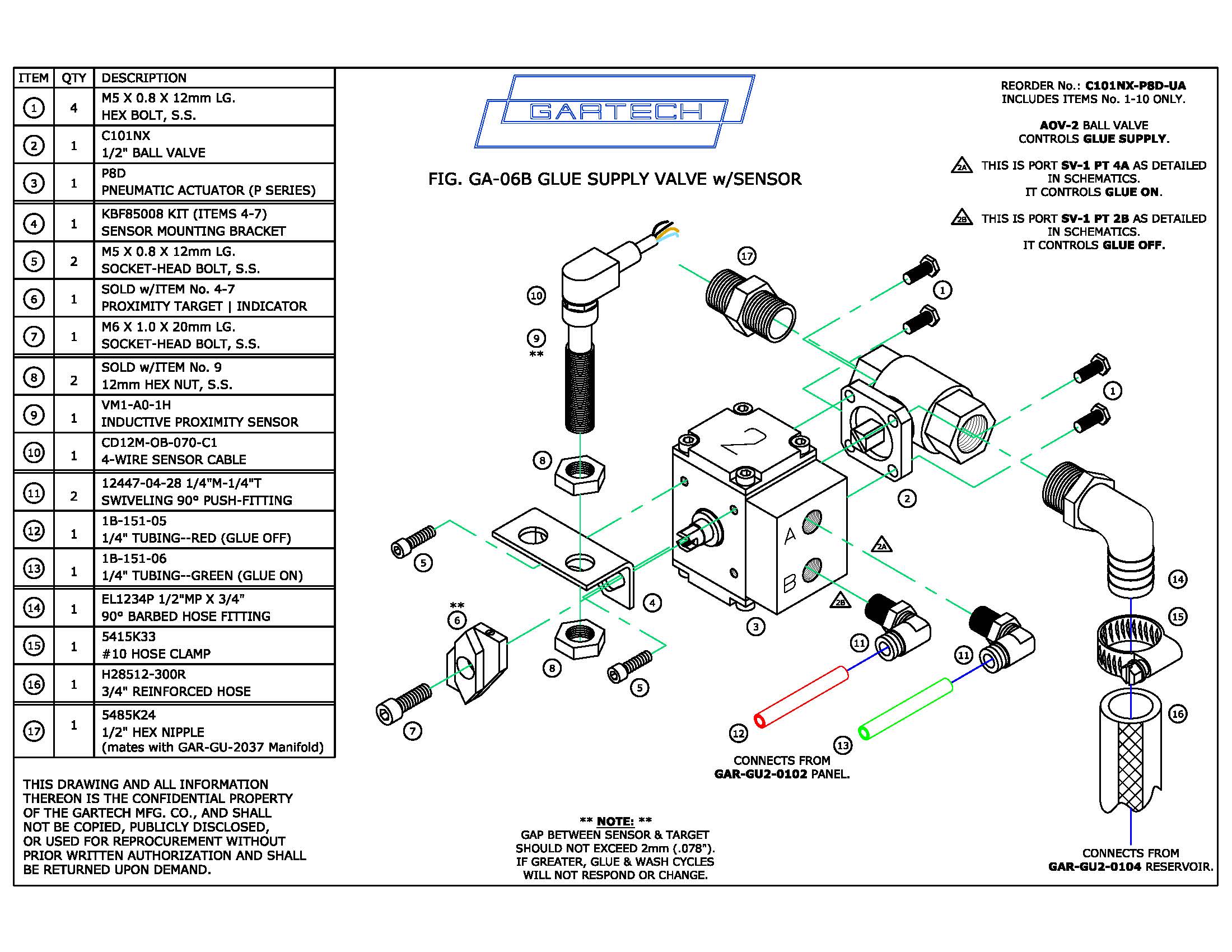
Today we’re focusing on the inductive proximity sensor (VM1-A0-1H) fitted to the uppermost ball valve on the Glue Manifold (specify C101NX-P8D-UA when re-ordering as the O-series “O8D” has been discontinued). When facing the glue shoes and glue wheels, you’ll often find this valve on the top right column of the Glue Manifold. The metallic target and the red and green tubing connected to this ball valve makes it easier to identify.
The exterior of the barrel is threaded like a bolt, in this case, a 12mm diameter tube with a 65mm length. At one end, here the top, a 4-pin M12 quick-disconnect is fitted with a shielded-cable. It’s this cable that’s hard-wired into the Control Panel as “Limit Switch” or “Prox. Sensor.”
At the opposite end of the 12mm barrel, here the bottom, a coated surface allows for reading. When engaged, you’ll notice a small amber light on the barrel body.
Often, when we receive phone calls from customers who cannot get their Glue Systems to switch from Upper to Lower Glue, or to switch from Glue Cycle to Wash Cycle, the culprit is one of the simplest items to overlook: the proximity sensor.
How this sensor works, is that it reads a metal screw in the target puck on the manifold ball valve that controls the Glue On (green air tubing) and Glue Off (red air tubing).
Now that we’ve gone through all of the descriptive specs, let’s focus on what matters: the gap. The sensor reads a distance of up to 2mm (or .0787″). That’s little more than 1/16″ if you aren’t accustomed to metric measurements. If it exceeds this gap, the sensor can no longer read the target. No matter how often or how hard you push the buttons on the panel, it isn’t going to change functions.
Standing next to a flexo while it’s running is about like waiting next to a railroad track as a train passes. The vibration does affect the two hex nuts that keep the sensor in position. Every Glue Manifold is tested for proper reading a minimum of two times before it ever gets shipped to a customer. The hex nuts are treated with Loctite Threadlocker Red 271, too. Still, the constant vibration takes a toll–even when everyone has kept their hands off of it.
The solution? A quick-and-easy gauge for setting the gap is a stainless steel flat washer for a 1/4″ bolt. Depending on the grade, the thickness ranges from .043″ to .060″, well within the range we want. Note: We don’t include zinc-plated washers because some grades exceed .080″ in thickness. While this could still work, we prefer to set the gap narrower, so it doesn’t vibrate out of range as sudden.
When you replace the sensor, we offer a kit that includes the hex nuts, a new target, and the angle bracket. This lets you set everything on site.
Need a printable layout? Click here for a parts layout of this valve with the sensor. And, be sure to scroll down for more pictures.
This picture shows the desired gap when engaged.
(This system wasn’t under power at the time, otherwise, you’d see the light on the barrel.)

Notice the white-coated end of the sensor barrel below?
This is the portion that seeks the target and transmits the signal to the Control Panel. When assembled, the flathead bolt in the black and yellow 2-piece target on the Ball Valve should line-up with the end of the barrel.
 Still having trouble? Give us a call or send us an email.